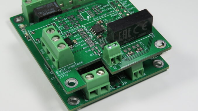
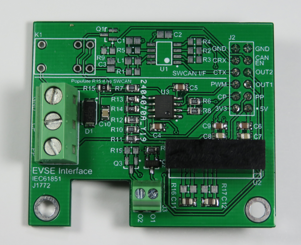
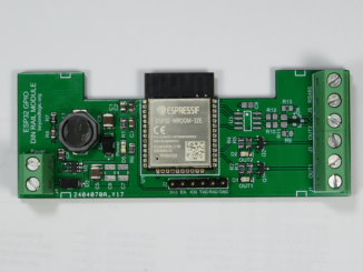
This is a prototype IEC61851 / J1772 EVSE (Electric Vehicle Supply Equipment) Interface intended to connect to a 3.3V micro-controller of your choice. It was originally designed to piggyback on the Electric Vehicle Charge Controller PCB (shown above) and utilise the on-board Microchip dsPIC33 MCU. Firmware for the dsPIC33 is currently working.
Code is now being developed for the ESP32. The ESP32 has WiFi capability and this will enable the EVSE to retrieve electricity market pricing or instantaneous PV solar generation data.
Below are selection of open source designs for EVSE. Some have been through multiple revisions and make a great starting point to learn from their findings.
Hardware – Theory of operation
Readers should be familiar with IEC61851 / J1772 signalling. If not, please refer to Wikipedia.
Control Pilot – Background
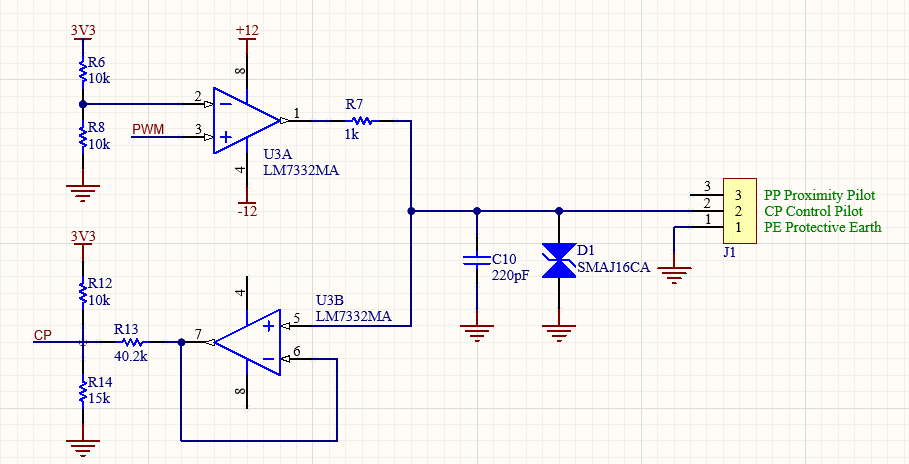
Below is a simplified version of the Control Pilot (CP) circuit. A relay, used to switch in SWCAN digital communications, has been removed to enhance readability.
The PWM input is a 3.3V digital input. Use an external microcontroller to generate a 1kHz ± 0.5% square wave used to advertise the available charging current. The duty cycle can be determined from the table below:
| Available Charging Current | Duty Cycle provided by EVSE (± 1%) |
| Use Digital Comms e.g. IEEE 1901 Power Line or Tesla SWCAN | 5% |
| 6A to 51A | 10% to 85% – Duty Cycle = Current (A) / 0.6 |
| 51A to 80A | 85% to 96% – Duty Cycle = (Current (A) / 2.5) + 64 |
Op-amp U3A (LM7332) will convert this to a ± 12V signal and drive the control pilot via a 1K series resistor. The LM7332 is a rail to rail op-amp with high output drive and has been used by SmartEVSE.
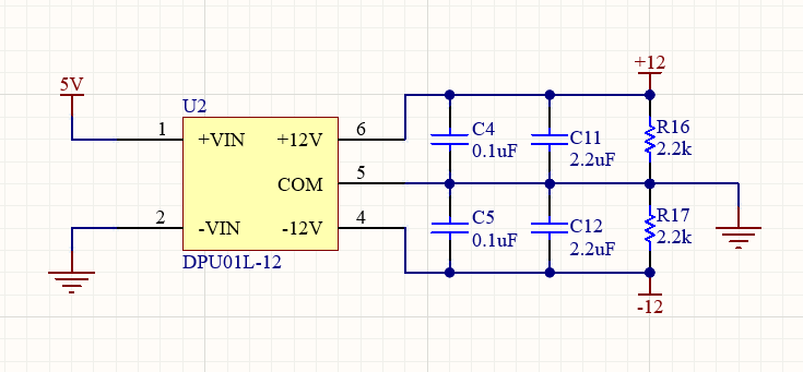
The ±12V is generated by a 1 watt Mean-well unregulated DC-DC converter (DPU01L-12) operating from a 5V supply. According to the datasheet the output should have an absolute accuracy of ± 3%, but load regulation may be poor. The IEC standard calls for a voltage tolerance of ±5%. It has been noted some open source EVSE designs have shifted from these DC-DC brick converters to a positive 5V to 12V DC-DC switcher and separate charge pump (e.g TC1044) to generate the negative rail from the positive.
Control Pilot Feedback (Status)
The vehicle will communicate back the status by loading the positive cycle of the control pilot. This will in effect produce the following voltages (acts as a voltage divider with the 1k resistor R7):
| Charging Status | Voltage at EV Socket | CP Output |
| Standby | +12V | 3.28V |
| Vehicle Detected | +9±1V | 2.89V |
| Ready (Charging) | +6±1V | 2.5V |
| No Power (off) | 0V | 1.72V |
| Error | -12V | 0.16V |
With a spare ½ op-amp left, U3B provides voltage buffering of the CP. R12/R13/R14 is designed to linearly convert ±12V to 0 to 3.3V suitable for feeding into an ADC.
PP (Proximity Pilot) – For Detachable Cable Assemblies
When a tethered cable is attached, the maximum current advertised by the EVSE should naturally not exceed the maximum capability of the charging cable. In this case, the maximum current is hardcoded, and the PP line is normally not connected back to the EVSE electronics.
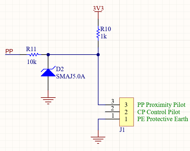
However, when an EVSE accepts detachable cables, it must first determine the maximum current carrying capacity of the cable. This is done via a resistor mounted in the plug between PP and PE of the detachable cable. (IEC states removable cables should have no release buttons). Both ends of the cable should have the same resistor value so both the EVSE and vehicle can determine maximum current capacity.
The PP analog output is used to determine the maximum current carrying capability of the detachable cable. This resistor acts as a simple voltage divider with R10.
| Resistor fitted to charging cable (Ohms) | Amps (Cable) | PP Output (Volts) |
| 1500 | 13 | 1.98 |
| 680 | 20 | 1.34 |
| 220 | 32 | 0.60 |
| 100 | 63 | 0.30 |
| 50 | 80 | 0.16 |
Tesla SWCAN Support
This board also includes experimental support for Tesla SWCAN (Single Wire Controller Area Network) communication. This is optional and does not need to be populated.
To enable this mode, set SWCAN_EN high. This will enable a relay and switch the control pilot line to the SWCAN transceiver. SWCAN_RX and SWCAN_TX is the output from the transceiver and should be wired to a CAN Controller.
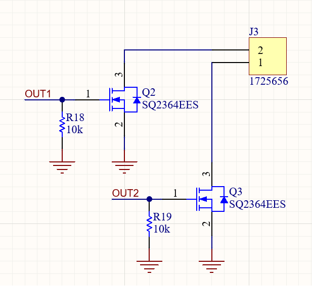
Contactor Driver / General Purpose Open Drain Outputs
The board includes two 60V open drain MOSFET outputs, one intended to operate the mains contactor to enable power to the vehicle. The SQ2364EES has a maximum drain current of 2A. (Maximum power is 3 watts, but with a RDSON @ 1.5V of 0.245ohms, you are unlikely to exceed it.)
Normally you would include some back EMF protection across the coil, however we do not have access to the coil supply. The contactor currently being used has in-built protection varistor to suppress back EMF.
Connector I/O
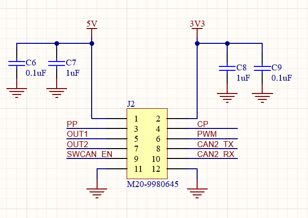
Below is the pinout for the I/O connector. The PCB requires both 5V and 3.3V to operate. I/O is 3.3V.
| Name | Type | Description |
| 5V | Power | 5V Power Supply. Provides 5V for +/-12V Switcher, SWCAN transceiver and relay. |
| 3V3 | Power | 3.3V Power Supply |
| PWM | Digital Input | 1kHz Control Pilot signal. Duty cycle specifies available charging current. |
| CP | Analog Output | Control Pilot feedback. Used to determine vehicle state. |
| PP | Analog Output | Proximity Pilot. Reports maximum current carrying capability of detached cables. Not used when implemented with tethered cable. |
| OUT1 | Digital Input | Enable MOSFET output (1). |
| OUT2 | Digital Input | Enable MOSFET output (2). |
| SWCAN_EN | Digital Input | High enables Single Wire CAN Mode. Pulled low by 10k. |
| SWCAN_RX | Digital Output | Receive output from SWCAN Transceiver. |
| SWCAN_TX | Digital Input | Transmit input to SWCAN Transceiver. |
Design Files
Design files can be downloaded from the Circuit Maker website. Circuit Maker is a free EDA tool from Altium.
- Open in Altium 365
- EVSE Interface version A.1 Gerbers – PCB (Zip)
- EVSE Interface version A.1 Schematics (PDF)
- EVSE Interface version A.1 Bill of Materials (XLSX)
Source Code
Open Source Firmware based on the dsPIC33EP can be found the following GitHub Repository:
Safety Notes
This is a prototype interface module and not a finished product. Reproduction should only be attempted by suitably competent persons.
Most EVSE will have a built-in RCD (Residual Current Device) or GFCI (Ground Fault Circuit Interrupter) Type-A, 30mA trip.
Type-A RCD’s will not trip or could get saturated by DC leakage currents. Some jurisdictions require Type-B (or Type-EV) RCDs that will trip with DC leakage. This may also be provided as a built-in RDC-DD (Residential Direct Current Detection Device) conforming to IEC62955.
Other jurisdictions may also require PEN (Protective Earth and Neutral) fault protection.

Gerber files are missing
Hi, where can I buy a Prototype IEC61851 / J1772 EVSE Interface?
https://item.taobao.com/item.htm?spm=a1z10.3-c-s.w4002-21282414209.53.696a6fb3LLG9mM&id=749609587517
Hi Craig! First of all congratulations for this project.
I’m trying to replicate it but I can’t find the LM7332 in stock. Could you suggest me a replacement?
Thanks!
Thanks Craig
I was writing up a post about the circuit required for the minimum requirements for a circuit for an EVSE when while describing the functionality I realised it would be easier to describe the sub-circuit functionality and the expected results of the EV feedback if I explained the circuitry inside the vehicle first.
This post I have written contains the basic circuits and functionality to build a Manual EV emulator at home, The device I have described has the same functionality and operation as commercial devices used by EVSE installers to confirm the functionality on site.
https://philipmcgaw.com/diy-manual-ev-emulator/
Incredible project, thank you very much for sharing it. I have been studying for a while and I am prepared to replicate it, I have all the components and I have designed a single-sided PCB based on your schematics, but I have a question, what is the purpose of the 220pf C10 capacitor?
Thanks!
Hello, I would like to use the gerber files to get one printed, but the link to download is not working, would you be kind to sent it for me?