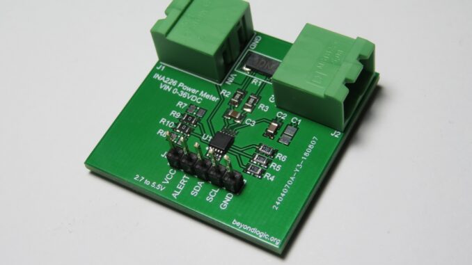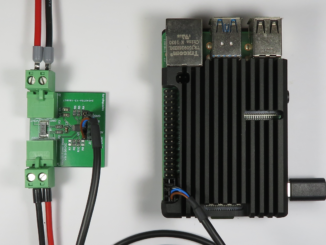
A breakout board for a DC Voltage/Current/Power Meter based on the popular INA226 36-V, Bi-Directional, Ultra-High Accuracy, I2C Current/Power Monitor with Alert.
While many INA226 breakout boards are available from eBay/Banggood/AliExpress (e.g. CJMCU-226) they do not allow for easy connection of the bus voltage. In addition, we list different shunt resistor values you can use to customise the current range to best suit your application.
Specifications
- Input Voltage: 0-36V.
- Current Measurement: +/- 20A. (Phoenix Contact connectors rated at 12A)
- Bus: I2C
- ADC Resolution: 16bits
- Bus Voltage Resolution: 1.25mV
- Current Resolution: 625uA
Design Notes
The device is powered via a separate 2.7 to 5.5V power supply connected to J3. Typical power consumption is just 330uA @ 3.3V.
The signed 16-bit bus voltage register has a least significant bit/resolution of 1.25mV allowing for a full scale voltage of +/-40.96V. Note, however that the device is rated to 36V (40V absolute maximum) on the input pins.
The analog input for the shunt resistor accepts a full scale voltage of 81.92mV. With a 4mOhm shunt resistor, a maximum current of +/-20.48A can be measured with a 625uA resolution.
Shunts
Below is a table of suggested shunts.
| Shunt Resistance | Max Current (A) | Part Size | Part Number | Power Rating (W) | Max Power (W) |
| 0.003 | 27.31 | 2512 | ERJMS4SF3M0U | 3 | 2.24 |
| 0.004 | 20.48 | 2512 | ERJMS4SF4M0U | 3 | 1.68 |
| 0.005 | 16.38 | 2512 | ERJMS4HF5M0U | 3 | 1.34 |
| 0.006 | 13.65 | 2512 | ERJMS4HF6M0U | 3 | 1.12 |
| 0.007 | 11.70 | 2512 | ERJMS4HF7M0U | 2 | 0.96 |
| 0.008 | 10.24 | 2512 | ERJMS4HF8M0U | 2 | 0.84 |
| 0.009 | 9.10 | 2512 | ERJMS4HF9M0U | 2 | 0.75 |
| 0.010 | 8.19 | 2512 | ERJMS4HF10MU | 2 | 0.67 |
Design Files
Design files can be downloaded from the Circuit Maker website. Circuit Maker is a free EDA tool from Altium.


Good day.
Trust that all is well.
I am new to Raspberry Pi and have (outdated) experience with designing/building circuits, circuit boards, etc.
I am interested in building/assembling a system, based on Rasberry Pi to measure AC/DC Voltage & Current of a small off-grid 48V DC PV system, 12V DC battery storage, and Inverter to 120V AC.
Will your boards accommodate this? I have shunts.
Would also like to measure the ambient Temperature of the batteries/environment where all the gear is set up. Do you have such interface boards/sensors as well?
Can you please share pricing, ordering information?
Lastly, what model & configuration of Raspberry Pi would you recommend for such a project (or point me to online resources to utilize)?
Thank you very much.