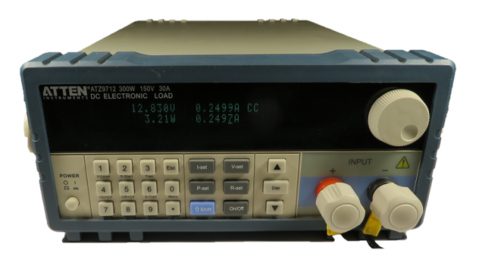
The Atten ATZ97 / Maynuo M97 Series programmable DC loads has a RS-232 port that can be used for instrument control and acquisition. Rather than using more conventional text based SCPI (Standard Commands for Programmable Instruments) commands, these instruments use Modbus, a protocol designed for PLCs (Programmable Logic Controllers).
The M97 series loads come bundled with “M9700 Load Monitor Software” that does a reasonable job in controlling the DC load and recording data.
However, I wanted to use the DC load in a test setup with a DC Power Supply to plot the efficiency of DC-DC converters.
To accomplish this task, I wrote routines in Visual C++ to allow control of the instrument from a Windows based PC.
The Protocol
The communications protocol is loosely defined at the end of the user guide.
Control is achieved through a series of registers and single bit flags (called coils in Modbus).
Bit Flags (coils)
The majority of the flags are read-only status flags, for example, over-current, over-voltage, over-power, over temperature. However, a handful allow control such as switching the voltage measurement to the rear terminals, and turning on the load/input.
To manipulate these flags, two functions are available – ReadCoil() and WriteCoil().
Registers
The majority of registers are 4 bytes double-precision floats (double) used to store current/voltage/resistance/power set-points and to read measured values.
To manipulate these float registers, ReadFloat() and WriteFloat() functions are available.
Lastly, there are a couple of 2 byte registers. The most notable is the command register (CMD). Writing to this register will set the DC Load to the desired function (constant-current, constant-voltage, constant-resistance etc).
To obtain the current state, one can read the SETMODE register.
To manipulate the integer registers, ReadRegisterInt() and WriteRegisterInt() are available.
Source Code
The source code for this project can be obtained from https://github.com/craigpeacock/ATZ9712


Be the first to comment