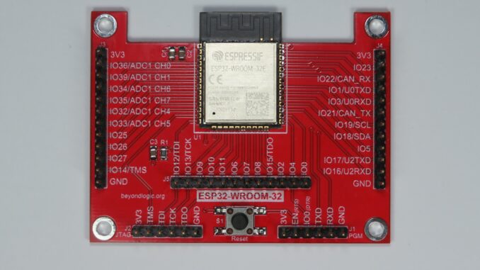
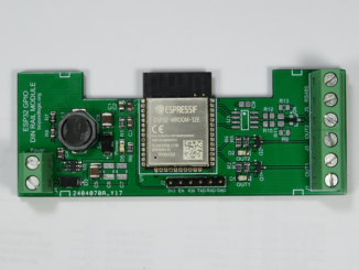
Featured here is a breakout board for the Espressif Systems ESP32-WROOM modules incorporating a MCU with WiFi and Bluetooth connectivity.
The board is designed to be minimalist and targeted towards battery operated devices. As such, no voltage regulator is included.
For those not already familiar with the ESP32, this SoC offers the following features:
- Xtensa dual-core 32-bit LX6 microprocessor running up to 240MHz.
- 448KB rom for bootloader and core functions.
- 520KB SRAM (plus 16KB SRAM contained in RTC).
- 802.11b/g/n WiFi up to 150 Mbps.
- Bluetooth V4.2 BR/EDR and Bluetooth LE.
- 3.0 to 3.6V operation.
A datasheet for the latest ESP32-WROOM-32E modules can be found here.
Various versions of the ESP32-WROOM-32 module exist. The latest -32E version incorporates the new ECO V3 silicon wafer (ESP32-D0WD-V3). V3 includes some silicon bug fixes, but its major improvement is secure boot and flash encryption.
Firmware Development
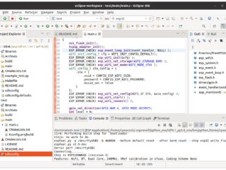
The official development framework for the ESP32 is the ESP32 IDF (IoT Development Framework). Here is a tutorial in Getting Started with the Espressif esp-idf & Eclipse IDE
The ESP32 is also a popular target for Arduino. An Arduino core can be found at the following Github repository complete with instructions on how to add it to the Boards Manager:
https://github.com/espressif/arduino-esp32
Programming
The ESP32 contains an UART bootloader in ROM. The bootloader can be started by holding GPIO0 low during a reboot. The default bit rate is 115,200 8N1.
The following pins are used for programming using the bootloader:

Esptool.py can automatically reset the ESP32 and enter the bootloader using RTS and DTS. Some terminal programs may assert RTS and holding the ESP32 in reset. Disabling hardware flow control should avoid this problem.
Many development boards use additional glue logic to prevent this from occurring.
Debugging with JTAG
In addition to the UART Bootloader, the ESP32 can also be programmed via the JTAG interface.
https://docs.espressif.com/projects/esp-idf/en/latest/esp32/api-guides/jtag-debugging/index.html
Battery Operation
A key purpose of this board is to test low power modes and battery operation.
While ESP32 silicon can support operating on voltages from 2.3V to 3.6V, the SPI flash found in the VROOM modules don’t like voltages under 3V.
A LiFePO4 cell is probably the perfect cell for the ESP32, with a voltage range of 2.5 volts to 3.65 volts. The LiFePO4 chemistry has a flat roll of curve and stays over the minimum 3.0V required for the SPI flash for most of the discharge cycle.
Antenna
The ESP32-WROOM-32 module comes in two variants featuring different antenna configurations. The ESP32-WROOM-32E incorporates a PCB antenna.
The cutout under the antenna is in accordance with recommendations from Espressif. Please refer to the ESP32 Hardware Design Guidelines, section 3.1.2 Positioning an ESP32 Module on the Base Board.
The ESP32-WROOM-32EU has a IPEX (also known as u.FL) connector for use with an external antenna. The module is 6.3mm shorter and doesn’t protrude over the end of the PCB.
Design Files
Design files can be downloaded from the Circuit Maker website. Circuit Maker is a free EDA tool from Altium.
- Open in Altium 365
- ESP32 Breakout version 1.A.4 Gerbers – PCB (Zip)
- ESP32 Breakout version 1.A.3 Schematics (PDF)
- ESP32 Breakout version 1.A.3 Bill of Materials (XLSX)
esptool
esptool is used for loading (flashing) compiled binary code onto the ESP32. It is normally installed as part of your programming environment (esp-idf, Arduino, PlatformIO) and doesn’t need to be manually installed. However, it is helpful in programming precompiled firmware such as Tasmota or ESPEasy.
Quite a few different programming tools exist for the ESP32 (and ESP8266) across multiple platforms (Linux, Windows, Mac) and in different forms – precompiled binaries, Python etc.
Many are maintained by the community and may not be as extensively tested, robust and polished as they should be. Some have different switches and options, others have graphical user interfaces in an attempt to make them easier to use, only to fail and provide next to no debugging information.
To prevent frustration and lost hours, I try to only support the esptool.py supported by Espressif. This programming tool is written in Python and is open source and platform independent.
Windows
If you don’t have Python installed on Windows, you will need to download and install the latest version.
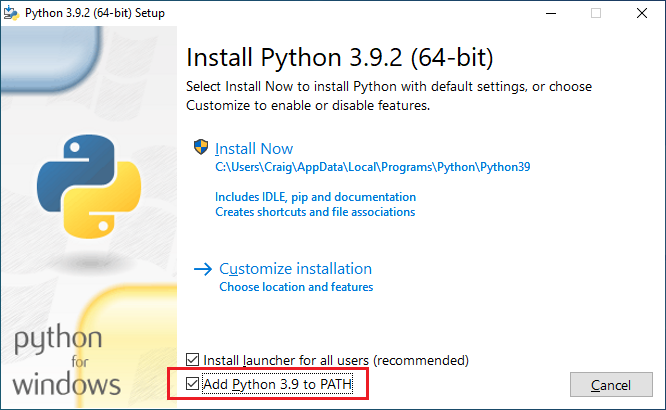
To make things easier, you may want to Add Python 3.9 to your PATH.
Linux
On many Linux distributions, you can install python with
# sudo apt-get install python3 python3-pip
Depending upon your distribution, it many also be necessary to grant yourself rights to the serial port and log out to become effective:
# sudo usermod -a -G dialout $USER
ESPtool.py
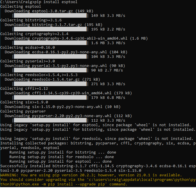
Once Python has been installed, you can use the Package Installer for Python (pip) to install ESPtool.
pip will also fetch any prerequisites required – bitstring, cryptography, ecdsa, pyserial, reedsolo, cffi, six and pycparser and install these to provide you a working installation.
pip install esptool
Flashing
To erase your ESP32, us the erase_flash command. The serial port is provided using the -p switch.
C:\Users\Craig\esptool.py -p COM6 erase_flash
esptool.py v3.0
Serial port COM6
Connecting....
Detecting chip type... ESP32
Chip is ESP32-D0WD-V3 (revision 3)
Features: WiFi, BT, Dual Core, 240MHz, VRef calibration in efuse, Coding Scheme None
Crystal is 40MHz
MAC: 7c:9e:bd:cf:6f:70
Uploading stub...
Running stub...
Stub running...
Erasing flash (this may take a while)...
Chip erase completed successfully in 16.5s
Hard resetting via RTS pin...
To program the ESP32 use the write_flash command. It takes two arguments <address> <filename>. In most cases you will want to load your code from address 0x0.
Below is an example of loading a precompiled binary of ESPEasy:
C:\Users\Craig\esptool.py -p COM6 write_flash 0x0 ESP_Easy_mega_20210223_normal_ESP32_4M316k-factory.bin
esptool.py v3.0
Serial port COM6
Connecting....
Detecting chip type... ESP32
Chip is ESP32-D0WD-V3 (revision 3)
Features: WiFi, BT, Dual Core, 240MHz, VRef calibration in efuse, Coding Scheme None
Crystal is 40MHz
MAC: 7c:9e:bd:cf:6f:70
Uploading stub...
Running stub...
Stub running...
Configuring flash size...
Compressed 1786640 bytes to 985718...
Wrote 1786640 bytes (985718 compressed) at 0x00000000 in 87.6 seconds (effective 163.1 kbit/s)...
Hash of data verified.

Leaving...
Hard resetting via RTS pin...

I’m glad I found this article. I am my application is using the ESP32-WROOM-32E and I am having the very problem you describe. I am having great difficulty getting it to program through the TLL interface. I am using just TX and RX and manually resetting the board (EN low) and putting it into boot mode (IO0 low before releasing EN). The ESP32 just times out. I’m pretty sure the ESP is indeed in download mode because it sends a confirmation through the serial port before the port is closed by the downloader and (presumably) reopened for the download. Any help you can provide would be greatly appreciated. (My application is also on Circuit Maker.)
Robert, One of the best things you can buy is the ESP-Prog for $12USD. It includes the glue logic for Enable/GPIO0.